
File list
This special page shows all uploaded files.
| Date | Name | Thumbnail | Size | User | Description | Versions |
|---|---|---|---|---|---|---|
| 00:04, 24 April 2026 | TechRepo-wordmark.svg (file) | 7 KB | Admin (talk | contribs) | A wordmark of Astronautics and Rocketry Club's Technical Repository. Designed by Thitut Uhthalye | 1 | |
| 04:45, 24 April 2026 | LD-A1 Injector dimension.pdf (file) | 501 KB | Admin (talk | contribs) | Brief technical drawing cut-out of the injector element in LD-A1 injector head | 1 | |
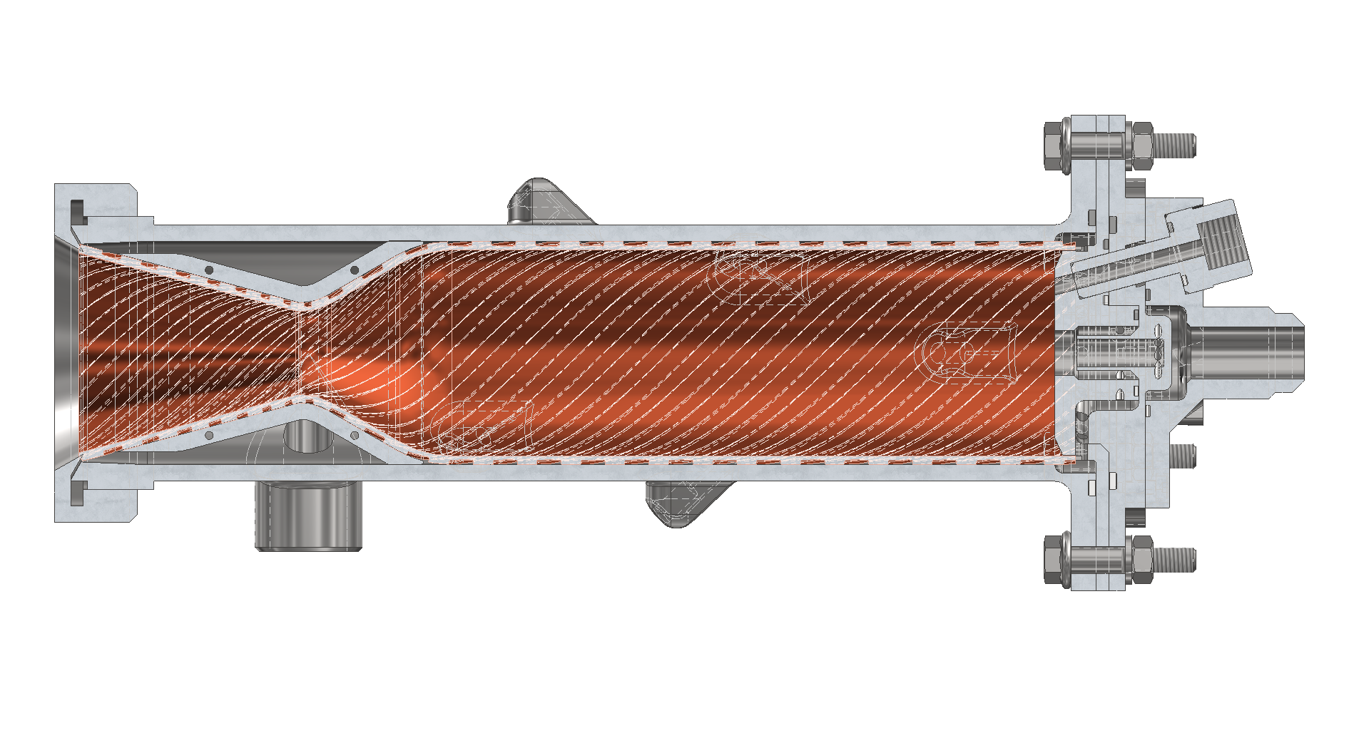
| 04:51, 24 April 2026 | LD-A1 half section.png (file) |  |
445 KB | Admin (talk | contribs) | A half-section CAD view of the LD-A1 engine from Autodesk Inventor | 1 |
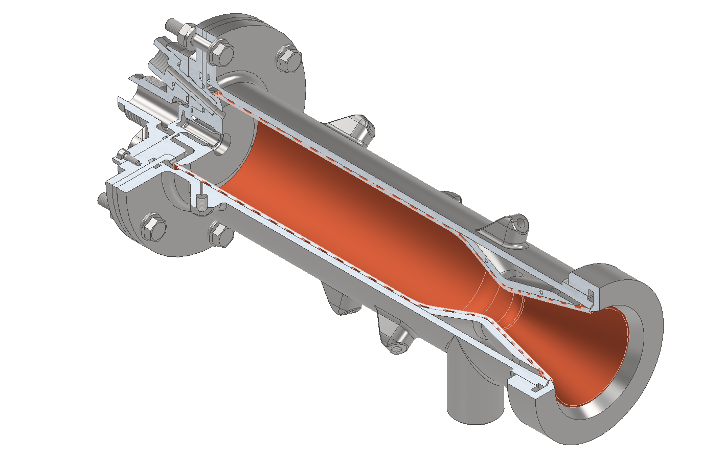
| 04:54, 24 April 2026 | LD-A1 quarter section.png (file) |  |
259 KB | Admin (talk | contribs) | A quarter-section CAD view of the LD-A1 engine from Autodesk Inventor | 1 |
| 05:27, 24 April 2026 | LD-A1 Instrumentation diagram.pdf (file) | 481 KB | Admin (talk | contribs) | Instrumentation diagram of LD-A1 engine | 1 | |
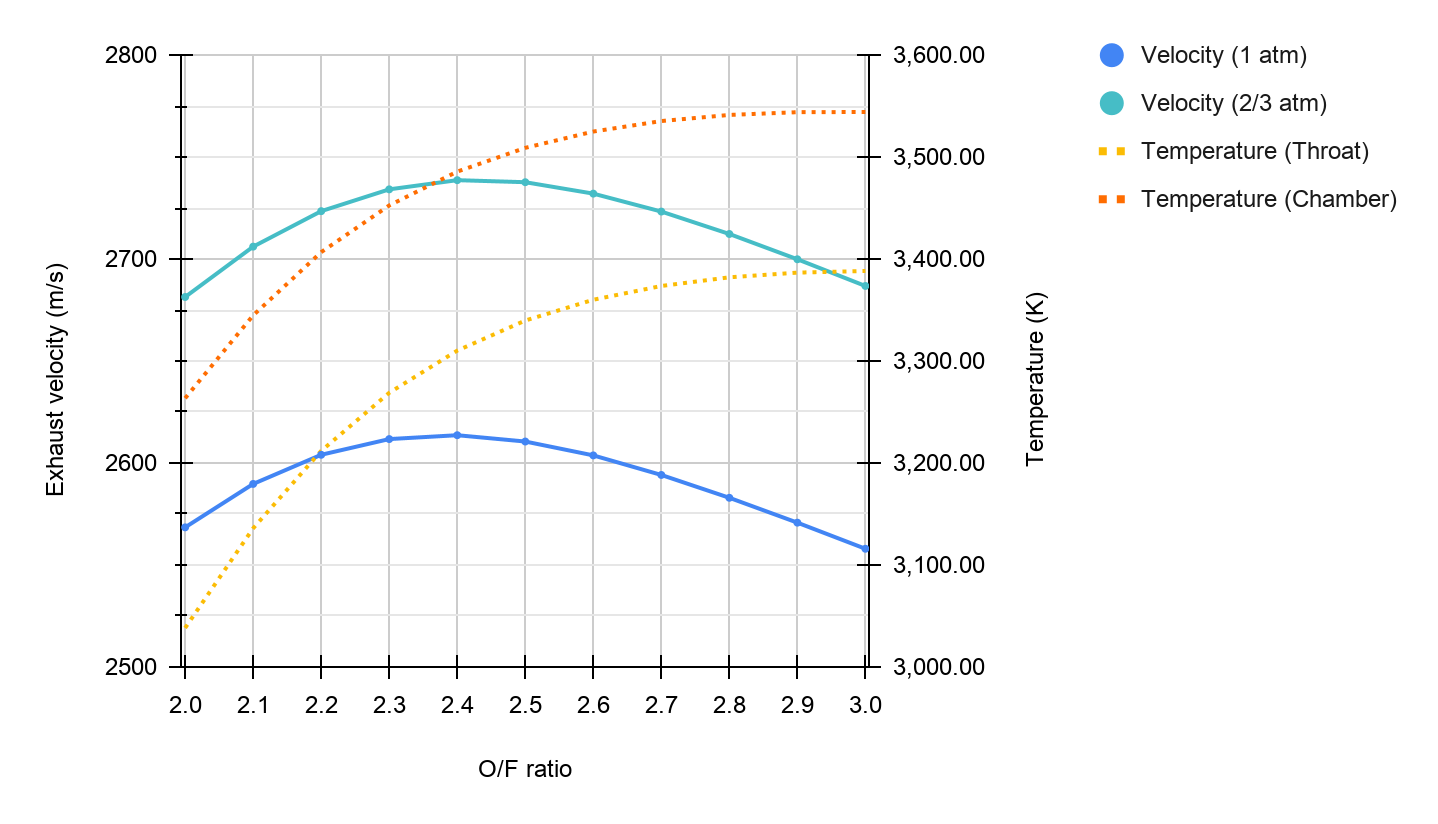
| 05:34, 24 April 2026 | LD-A1 CEA.png (file) |  |
87 KB | Admin (talk | contribs) | A plot between ideal exhaust velocity and oxidiser-fuel mixture ratio, and temperature a result from NASA CEA web application. | 1 |
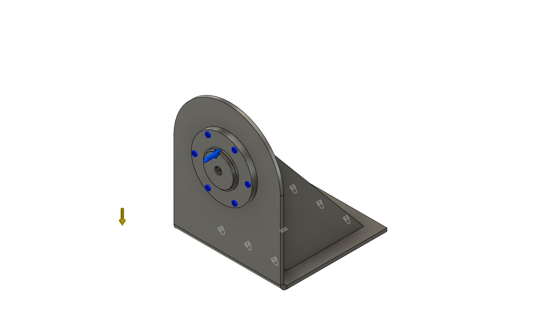
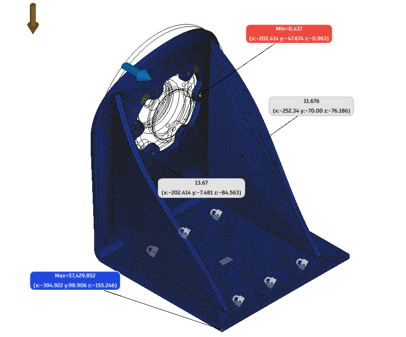
| 05:37, 24 April 2026 | LD-A1 Bracket Boundary Cond.png (file) |  |
148 KB | Admin (talk | contribs) | A CAD view of an FEA load and boundary conditions of the mounting bracket, exported from Autodesk Fusion | 1 |
| 05:38, 24 April 2026 | LD-A1 Bracket SF.png (file) |  |
154 KB | Admin (talk | contribs) | A view from an FEA load case in Autodesk fusion with the gradient displaying safety factors | 1 |
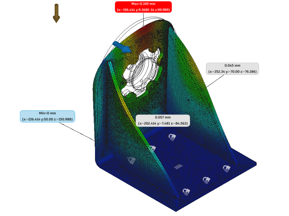
| 05:39, 24 April 2026 | LD-A1 Bracket Disp.png (file) |  |
241 KB | Admin (talk | contribs) | A view from an FEA load case in Autodesk fusion with the gradient displaying displacement magnitude | 1 |
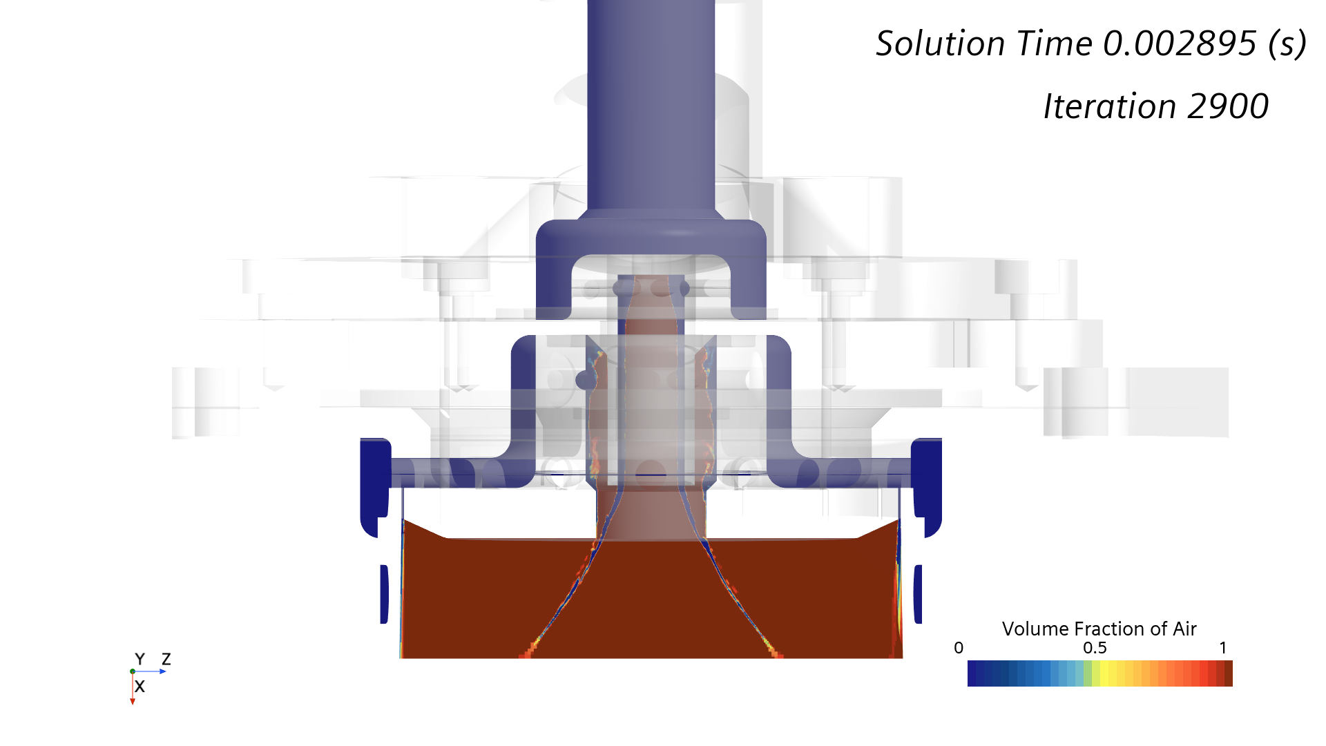
| 05:43, 24 April 2026 | R2S Swirl test@02900 VF.png (file) |  |
226 KB | Admin (talk | contribs) | A Hardcopy showing volume fraction of air scalar field from the 2900th iteration in LD-A1's swirl injector VOF CFD simulation | 1 |
| 05:44, 24 April 2026 | LD-A1 Jet A Temp.pdf (file) | 93 KB | Admin (talk | contribs) | A thermal plot from RPA showing temperature and heat flux distribution in LD-A1 thrust chamber. Jet A configuration | 1 | |
| 05:45, 24 April 2026 | LD-A1 IPA Temp.pdf (file) | 91 KB | Admin (talk | contribs) | A thermal plot from RPA showing temperature and heat flux distribution in LD-A1 thrust chamber. IPA configuration | 1 | |
| 05:47, 24 April 2026 | LD-A1 R2S von Mises.svg (file) |  |
94 KB | Admin (talk | contribs) | Plot showing the result of 1D stress calculation in LD-A1 thrust chamber, using thermal data from RPA. This plot shows von Mises stress and yield strength. | 1 |
| 05:48, 24 April 2026 | LD-A1 R2S SF.svg (file) |  |
62 KB | Admin (talk | contribs) | Plot showing the result of 1D stress calculation in LD-A1 thrust chamber, using thermal data from RPA. This plot shows safety factor on two calculation assumptions. | 1 |
| 05:49, 24 April 2026 | LD-A1 R2S combined hoop stress.svg (file) |  |
63 KB | Admin (talk | contribs) | Plot showing the result of 1D stress calculation in LD-A1 thrust chamber, using thermal data from RPA. This plot shows combined hoop stress (from thermal and pressure stress), from two different assumptions. | 1 |
| 05:55, 24 April 2026 | LD-A1 Injector water test.pdf (file) | 860 KB | Admin (talk | contribs) | Two figures overlaid with angle measurement showing the spray cone angle of LD-A1 injectors in preliminary water flow test. | 1 |